Dimensions of Close-type Glass Lined Reactors (mm)
Volume
(L) | 3000 | 5000 | 6300 | 8000 | 10000 | 12500 | 16000 | 20000 | 25000 | 30000 | 50000 |
| Item |
| DN | 1600 | 1600 | 1750 | 1750 | 2000 | 2200 | 2400 | 2400 | 2400 | 2600 | 2800 | 3200 | 3400 |
| D0 | 1120 | 1220 | 1220 | 1220 | 1400 | 1540 | 1680 | 900 | 900 | 975 | 1050 | 1200 | 1500 |
| D1 | 1750 | 1750 | 1900 | 1900 | 2200 | 2400 | 2600 | 2550 | 2550 | 2750 | 2950 | 3350 | 3600 |
| D2 | 2029 | 2029 | 2200 | 2200 | 2502 | 3744 | 2940 | 2812 | 2812 | 3060 | 3335 | 3866 | 4378 |
| D3 | 30 | 30 | 30 | 30 | 36 | 36 | 36 | 36 | 36 | 36 | 36 | 36 | 36 |
| D4 | φ95 | φ95 | φ95 | φ95 | φ110 | φ110 | φ110 | φ110 | φ125 | φ140 | φ160 | φ160 | φ180 |
| D5 | 65×6 | 65×6 | 80×6 | 80×6 | 95×8 | 95×8 | 95×8 | 95×8 | 98×8 | 95×8 | 110×l2 | 110×12 | 125×12 |
| D6 | 600 | 600 | 600 | 600 | 800 | 800 | 800 | 800 | 800 | 900 | 1100 | 1300 | 2000 |
| D7 | 450 | 450 | 450 | 450 | 510 | 510 | 510 | 560 | 560 | 650 | 650 | 810 | 940 |
| D8 | 1300 | 1300 | 1400 | 1400 | 1505 | 1645 | 1785 | 1785 | 1785 | 1925 | 2065 | 2345 | | |
| H | 2250 | 3275 | 2888 | 3244 | 3310 | 3513 | 3160 | 3495 | 3830 | 4640 | 5060 | 4900 | 6765 |
| H1 | 1060 | 1160 | 1200 | 1200 | 1200 | 1300 | 1500 | 1300 | 1300 | 1400 | 1500 | 1750 | 2200 |
| H2 | / | / | 800 | 900 | 900 | 950 | 640 | 375 | 600 | 650 | 750 | 600 | 1700 |
| H3 | 700 | 780 | 750 | 750 | 800 | 1300 | 1010 | 900 | 900 | 1000 | 1050 | 1150 | 1250 |
| H4 | 1550 | 1710 | 1500 | 1700 | 1700 | 1850 | 1610 | 2000 | 2350 | 2500 | 2650 | 2650 | 2950 |
| H5 | 200 | 200 | 200 | 200 | 355 | 340 | 315 | 315 | 315 | 330 | 250 | 240 | / |
| H6 | 1454 | 1535 | 1535 | 1682 | 1702 | 1822 | 1822 | 1822 | 1822 | 2594 | 2594 | 2734 | 3260 |
| B1 | 540 | 540 | 540 | 540 | 540 | 540 | 540 | 550 | 550 | 550 | 550 | 550 | 550 |
| B2 | 370 | 370 | 370 | 370 | 370 | 370 | 370 | 470 | 470 | 470 | 470 | 470 | 470 |
| Power (kW) | 5.5 | 7.5 | 7.5 | 11 | 11 | 18.5 | 18.5 | 18.5 | 22 | 22 | 22 | 30 | 45 |
Nozzle Specifications (mm)
Volume
(L) | 3000 | 5000 | 6300 | 8000 | 10000 | 12500 | 16000 | 20000 | 25000 | 30000 | 50000 |
| Item |
| DN | 1600 | 1600 | 1750 | 1750 | 2000 | 2200 | 2400 | 2400 | 2400 | 2600 | 2800 | 3200 | 3400 |
| a | 150 | 150 | 150 | 150 | 200 | 200 | 200 | 200 | 200 | 250 | 250 | 250 | 250 |
| b | 100 | 100 | 125 | 125 | 150 | 150 | 150 | 150 | 150 | 200 | 200 | / | / |
| c | 125 | 125 | 150 | 150 | 150 | 150 | 150 | 150 | 150 | 150 | 150 | 150 | 150 |
| d | 100 | 100 | 125 | 125 | 150 | 150 | 125 | 250 | 250 | 250 | 250 | 250 | 250 |
| e | 125 | 125 | 150 | 150 | 150 | 125 | 125 | 150 | 150 | 150 | 150 | 150 | 150 |
| f | 125 | 125 | 125 | 125 | 125 | 150 | 150 | 150 | 150 | 150 | 150 | 150 | 200 |
| h | / | / | / | / | / | 150 | 150 | 150 | 150 | 200 | 200 | 200 | / |
| M | 300× 400 | 300× 400 | 300× 400 | 300× 400 | 300× 400 | 300× 400 | 300× 400 | 300× 400 | 300× 400 | 300× 400 | 300× 400 | 300× 400 | 300× 400 |
| S | 125 | 125 | 125 | 125 | 125 | 125 | 125 | 150 | 150 | 150 | 150 | 150 | 150 |
| T1 | 100 | 100 | 125 | 125 | 200 | 200 | 200 | 200 | 200 | 200 | 200 | 200 | 250 |
| T2 | / | / | / | / | 150 | 150 | 150 | 150 | 150 | 200 | 200 | 200 | 200 |
| N1-3 | 65 | 65 | 65 | 65 | 65 | 65 | 65 | 80 | 100 | 100 | 100 | 100 | 100 |
| K1-3 | 65 | 65 | 65 | 65 | 65 | 65 | 65 | 65 | 65 | 65 | 65 | 80 | 80 |
Components
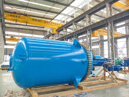
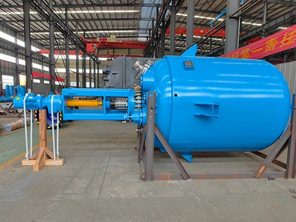
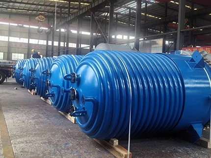
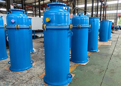
The glass-lined reactor is designed with integrated top head and vessel body instead of removable large cover. Manway is included for interior inspection and maintenance. The glass-lined reactor typically consists of glass-lined vessel body, jacket, agitator, agitator drive with motor and gearbox, mechanical seal, manway, inlet and outlet nozzles, temperature measurement system and bottom discharge valve. Baffles, dip pipes, thermowells, and other internal components can be equipped depending on the process.
How does a glass-lined reactor (close-type) work?
The glass-lined reactor is structurally enclosed with top nozzle for material feed, and allows the materials to undergo continuous mixing, mass transfer, and reaction with the working agitator. At the same time, the heating or cooling medium circulates through the jacket for rising/decreasing/constant temperature control, allowing for stable process under set temperature, pressure and time conditions.
After the reaction processes, the materials are discharged from bottom nozzle and sent to downstream processes such as filtration, crystallization, distillation, or storage. The integrated structure reduces the number of large body flanges and sealing joints and is more suitable for large-capacity chemical processes requiring reliable sealing and long-term stable operation.
 Jiangsu Gongtang